12-05-2021 - Show tank data
Proof of concept
Edit: 2022-01-27:
Added RFC1006 Port 102 documentation (ISO on TCP).
Added some extra CR.
Added axtra information about protocolls (at the end>(at the end>.
Mission:
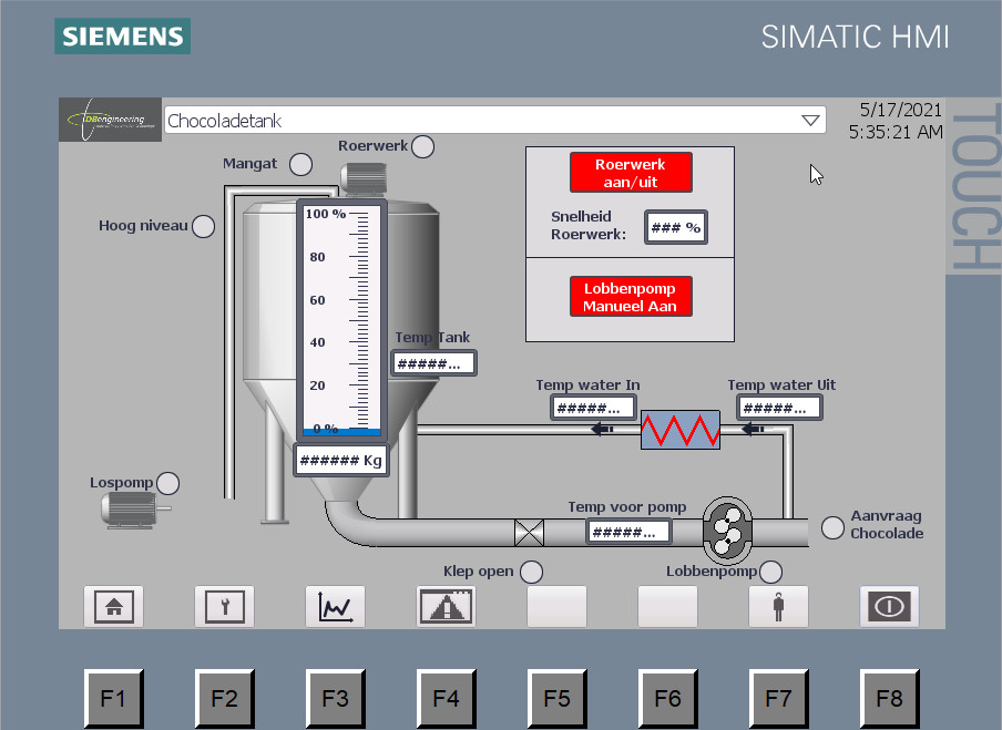
Show the level of the tank as shown in the picture on th HMI screen in the office area. The controls (PLC and HMI's) are in an B class network 192.168.xx.xx/16, the office is in a B class network 10.0.xx.xx/16. Both networks are not connectet to each other becaus of safety.
Solution:
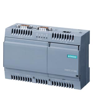
We will connect one side of a Siemens IoT2040 (6ES7647-0AA00-1YA2) to the PLC and the other side to the office network. In the IoT2040 we will access the PLC and catch the data and make it visible through a node red graph. Also we are going to provide .csv files for every week.
Step 1 - Flash the SD card.
Use the following image.
To copy the image on a SD card, use a program like Balena Etcher or Win32DiskImager.
Step 2 - Connect to the IoT
Start a program like PuTTY to connect to the IoT.
username = root
password = ****
Step 3 - Make basic settings
In the PuTTY terminal window give the following command after succesfull login.
root@iot2000:~# ifconfig
In the output you will see the basic settings of the ethernet connections, X1P1 and X2P1.
In this image, the IP address of X1P1 is set to 192.168.200.1/24 and X2P1 is set to DHCP.
Then give the next command in the terminal window of the IoT2040.
root@iot2000:~# iot2000setup
This wil bring you to the basic settings feature of the IoT.
Make the following changes:
Hostname = iot2000
Password = iot2000
Timezone = Amsterdam
Also enable node red on start up.
Then close the setup feature.
Step 4 - Check versions of Node-Red and NPM
Give the following commands:
root@iot2000:~# node -v
and
root@iot2000:~# npm -v
Note the versions of both programs.
Node version wil be v8.16.0 - do not update!
NPM version will be 6.4.1 - do not update!
Step 5 - Install node: node-red-contrib-s7
While the latest release of this node is not supported on node red on the IoT2040,
this node should be installed with a specific version, being 2.1.1.
Change to the directory where the nodes shall be installed:
root@iot2000:~# cd /usr/lib/node_modules
Check that you are in the right directory, then start installation of the node.
root@iot2000:~# npm install node-red-contrib-s7@2.1.1
Wait until the installation is finnished.
Reaction of the IoT should be like:
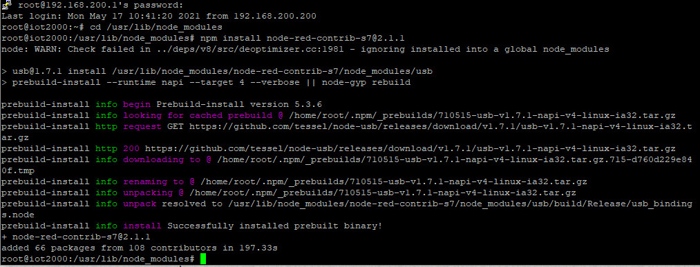
Of course, is installation only possible if you have an internet connection on one of the two LAN ports.
Check this with a command like below in the terminal window of PuTTY.
root@iot2000:~# ping google.com
Step 6 - Start node red.
Restart the IoT with the command:
root@iot2000:~# reboot
Rebooting and starting node-red will take a while.
Open a browser on a PC connected to the 192.168.200.1 port.
In this browser enter the url: (address of the IoT with port 1880 for node-red)
192.168.200.1:1880
This is the interface to node-red, running on the IoT.
Rebooting is ready if you can login with PuTTY to the IoT and if node-red starts in the browser.
If the browser announces a "This site can't be reached", then fully startup is not ready.
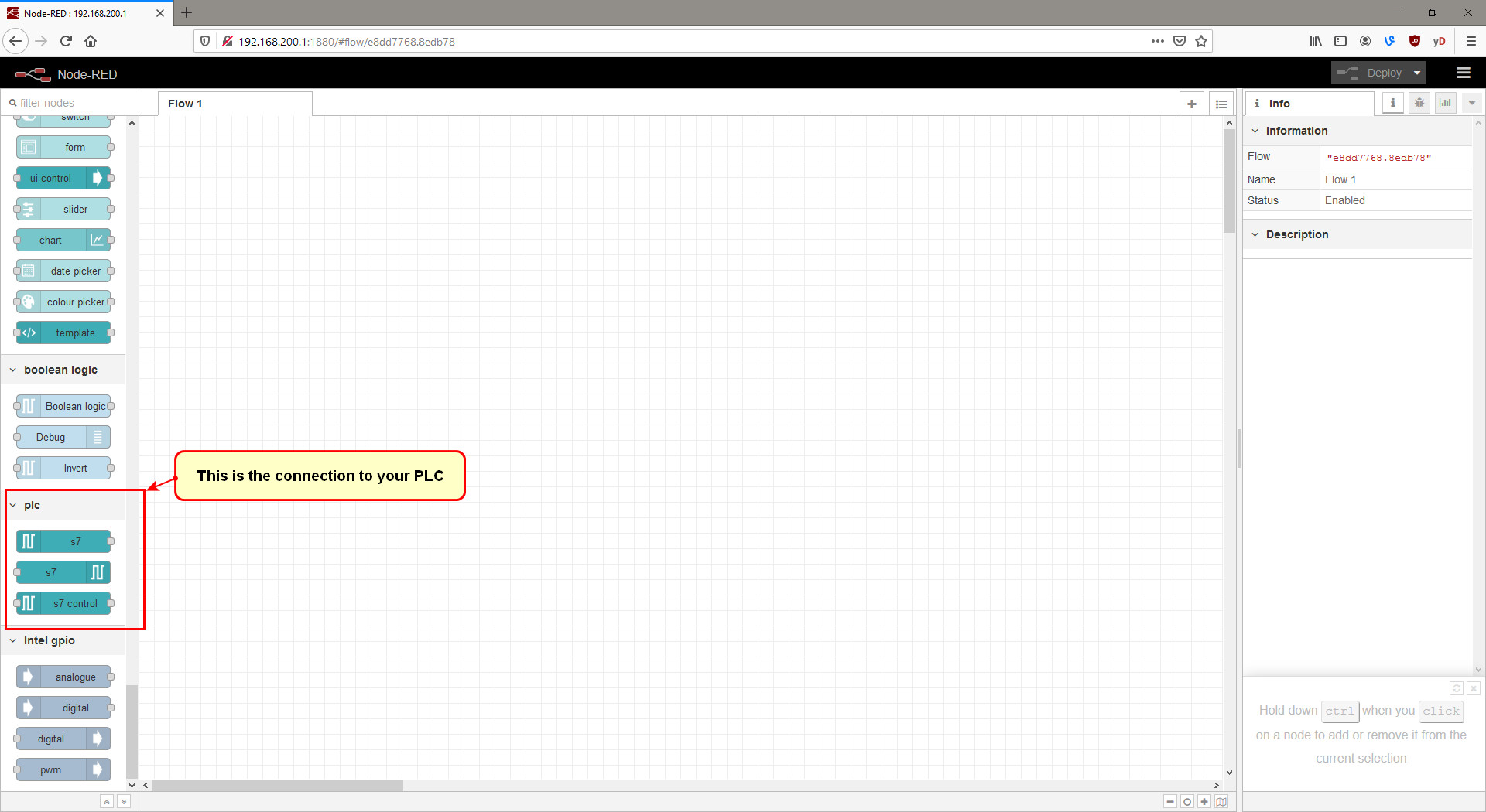
Check if the node-red-contrib-s7 node is installed correctly by searching for these nodes on the left side (see the picture below).
Step 7 - Prepare the PLC for access.
Now the PLC must be prepared for access with the node-red-contrib-s7 node.
For this two things have to be done:
1. If you want to access data in data blocks, then "Optimized block access" must be switched off for that DB.
2. And communication by PUT/GET must be enabled.
For detailed information see the following documentation on page 5.
This document also describes the installation of the node-red-contrib-s7 node, but that part of the documentation was written before an IoT2040 existed. Please follow step 5 of this blog to install the correct version of that node.
Step 8 - Access the PLC from IoT2040
Drag an "S7-in" node into the node red flow area and configure the node like shown below and press "ADD" and then "DONE".
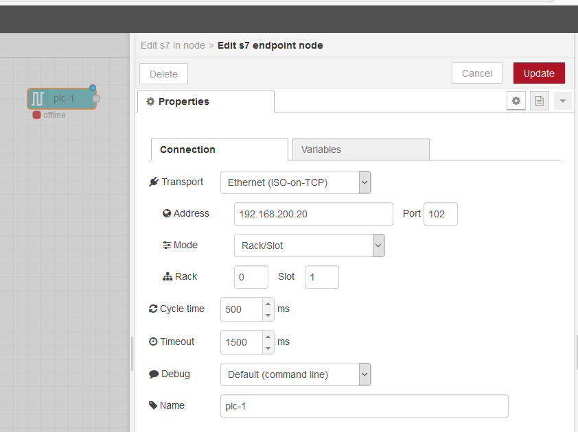
Deploy the flow. After that the node should show "online".
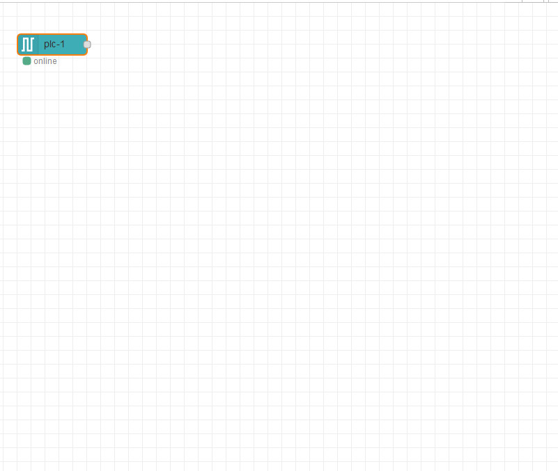
Step 9 - Define the variables to access.
In the PLC, we have defined a DB20, not optimazed.
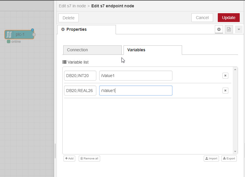
The DB contains an integer on data word 20 and a real on data double wordt 26.
How we can access these values is described in this document.
So to access the integer we must define access as "DB20,INT20".
To access the real we must define access as "DB20,REAL26".
See below picture.
Update and deploy the flow.
Now change the access to the PLC for the first node to:
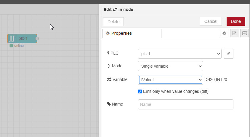
Copy the node and chage its access to the real, uopdate and deploy the flow, and see:
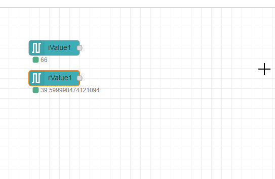
So the values are read from the PLC.
Step 10 - Show the readings in a graph.
Add a chart graph to the flow and configure like this.
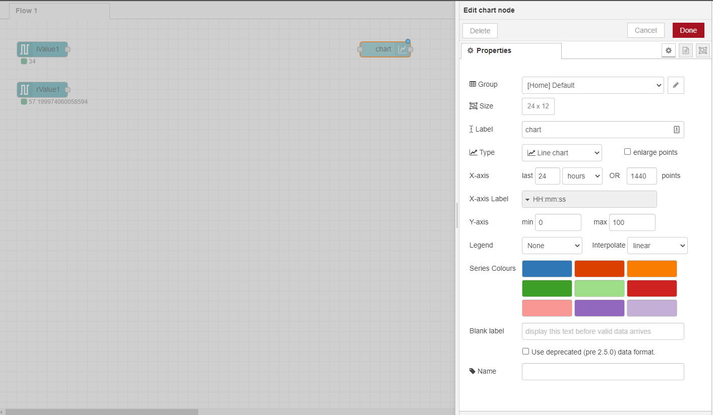
Connect the chart to the readings.

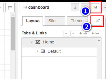
Start the user interface (right upper corner):
This is what is shown:
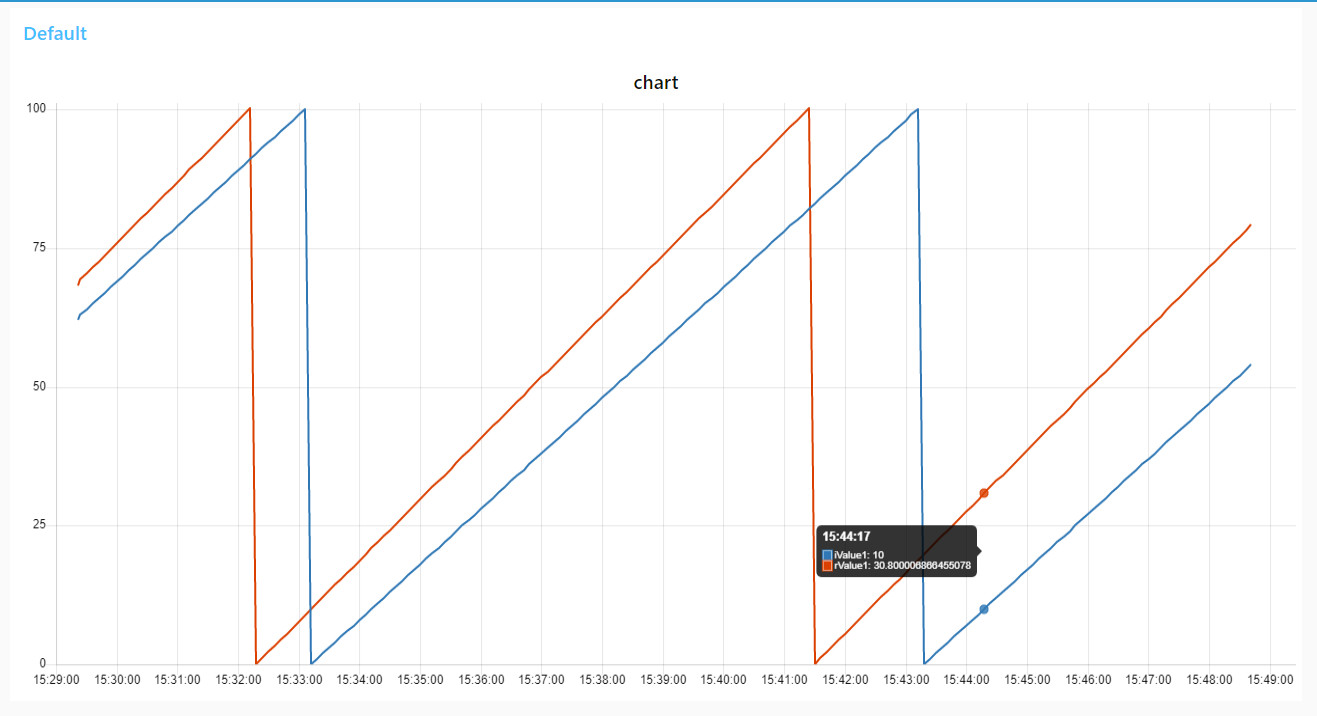
This can be shown from the X1P1 port and from the X2P1 port.
Here a download link to the completed json flow.
Protocolls
Here a link to the RFC1006 port 102 documentation about TCP on ISO protocoll.
Here a link to protocols in general.
The Siemens SIMATIC S7 ISO on TCP is descibed here.
The Siemens S7 Communication - Part 1 General Structure here.
The Siemens S7 Communication - Part 2 Job Requests and Ack Data here.
